




Bowie V2 Thrust Chamber Assembly

Bowie V2 — Engine Structural Analysis
Bowie V2 is Lehigh Rocketry's next liquid bipropellant engine, and it picks up right where Bowie V1 left off. V1 was a Half Cat style heat sink engine, and in 2025 we flew it, becoming the first team to launch a liquid biprop rocket on the East Coast after Tripoli changed its insurance policy to allow that class of vehicle. It was a huge milestone for the team, but if I'm being honest about it, we basically blind fired that engine. We got it off the pad and it worked, but we didn't actually have a real handle on the loads it was seeing while it ran.
V2 is the fix for that. On the propulsion side we're chasing higher combustion efficiency with an in house injector and pintle design, targeting a c* efficiency around 90 percent (c* is basically a measure of how well your propellants are actually combusting versus how well they theoretically could, and it's a clean way to define how hard you're pushing the engine). But the part I'm running is the structures side that has to keep pace with that, since a more efficient engine also means higher chamber pressure and higher temperature, and none of that is useful if we don't understand what it's doing to the hardware. The bigger goal past this engine is to get to a point where LURA can design and build its own engines with methods like additive manufacturing, and that only works if you actually understand what a part needs to survive instead of guessing and adding margin until it feels safe.
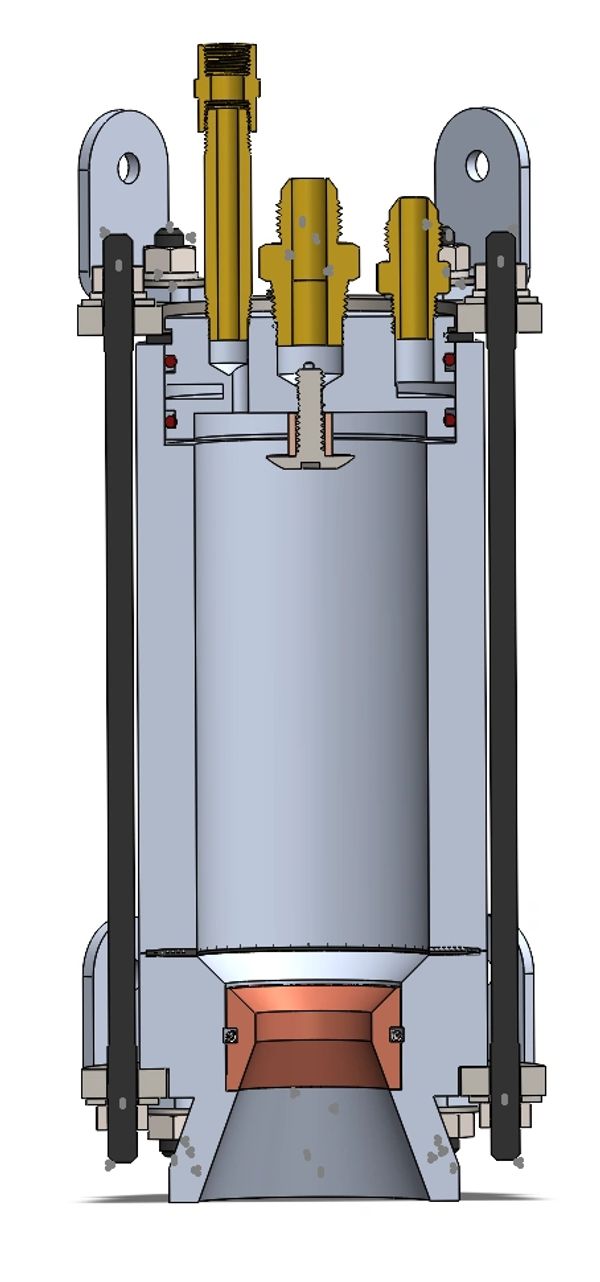
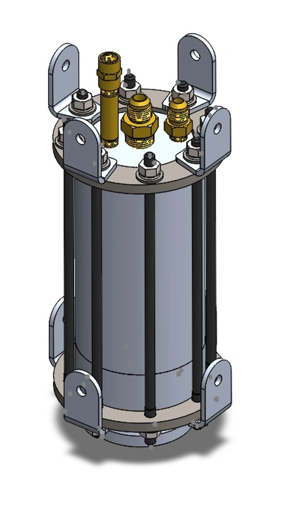
Here's the CAD for the engine, injector stack at the top feeding into the chamber, tie rods running the full length holding the assembly together against internal pressure, and the copper throat insert down at the nozzle since that's the section taking the worst thermal hit from the hot gas passing through.
Load cases for something like this don't come out of a table anywhere, you build them by actually talking to the people running the other parts of the system. I work across the injector, combustion, and nozzle teams to understand what the engine is actually doing, chamber pressure, flow, thermal environment, and then take a first principals approach to turn that into real structural loads. Since the driving variable here is c*, the load case is basically defined by how close we're pushing that number, the closer to 90 percent, the hotter and higher pressure the environment the structure has to survive.
For the nozzle specifically, the load path starts with 1D gas dynamics, tracking pressure, temperature, and velocity as the gas moves through the throat and out through the expansion section, which tells you what pressure and thermal load the wall is actually seeing at any given point along its length. From there it's straight mechanics of materials, turning those distributed loads into stress, bending, and deformation numbers I can actually work with.

Convergence and Verification
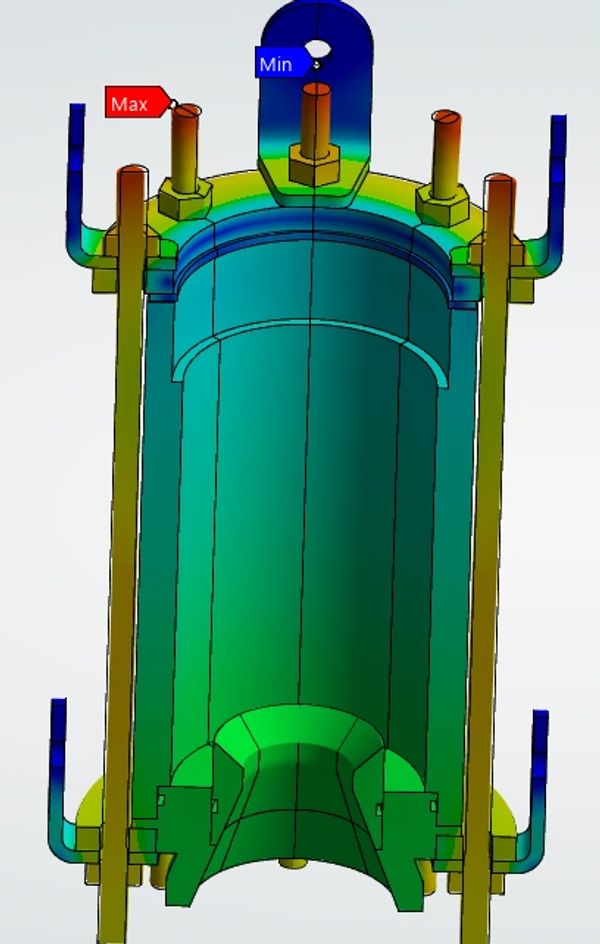
This run shows a converged model where I broke the full engine into radially symmetric sections instead of solving the whole assembly as one 3D model. The geometry and the loading both repeat all the way around the engine, so there's no reason to pay for a full 3D solve when a slice gives you the same answer for a fraction of the compute. That let me iterate on boundary conditions and mesh density a lot faster than waiting on a full model every time I changed something.
The tie studs got their own dedicated look, since how you model that joint changes the answer a lot. If you model the interface as bonded, the solver assumes the two surfaces never separate no matter what, which isn't how a real bolted joint behaves once preload or thermal growth gets involved. So I ran a sensitivity study comparing bonded contact against actual nonlinear contact to see how much that assumption was changing convergence behavior and the bending the model was predicting. From there I went to hand calcs, pulling the principal stresses straight out of the preload itself and setting margins off of that number directly, no FEA involved yet. Then I superposed those hand calcs with the max expected deformation coming off the flanges, combining the bending and axial stress by hand, which gave me an independent number to check the FEA against instead of just trusting whatever the solver spit out.
That comparison is what actually found the real issue, the flanges are the weak point in the load path, not the chamber wall and not the studs themselves like I originally expected. That finding is what's driving the flange resizing work right now, to get them correctly sized for the higher c* engine.

Validation and Moving Forward
Next step is instrumenting the engine for a planned static fire, specifically capturing chamber pressure and temperature, since those two numbers are what actually tell you how close the engine is running to that 90 percent c* target and what the real load environment looks like in practice, not just what the model predicts it should look like. That data is what validates the whole model against something real.
This whole project is basically my own version of the design, analyze, correlate loop I'd expect to run on propulsion hardware in industry, and that's the point of doing it this way instead of just building something and hoping it holds. Getting good at building a load case from first principals, building a model around it, and correlating that model against real data is exactly the skill set I want going into propulsion structures work.